Tuesday, November 2, 2010

the Back continued - gluing up and trimming

I spent a fair amount of time fitting the bottom to the rims, notching the rim and kerf lining to let the bracing end sit flush. Sorry no pics but it did come out nicely. One concern. I had been working on the back for a couple of days at this point and noticed it was cupping. Very noticable as I was dry fitting. I would seat the back at the neck end but then had to rock it to dry fit the heel end. Wasn't quite sure what kind of problems this could create. But carry on.

Similar to the top I thought I should clamp the back on first and then install the screws. This is dry fit and clamp trial # one. I don't know how long it took but it seemed to take forever to clamp and then drill and screw 20 something deck screws, especially trying to hand tighten each one at the end. This wouldn't do. I did another dry run. Because the screws had all been started in run #1 this one went faster and more smoothly. And I was smart enough to put a new battery on the power drill.


Before closing up the back I wanted to create a label of some sort to identify the guitar. No time or money for a fancy logo maker. I looked at tons of labels on line and in guitar stores. You can really spend a lot of time on this if you choose to.Well I chose not to. I sat down with my computer and the certificate program in Microsoft Word. I like the fender font and I like green and I had some left over rattle can burst amber and I came up with this. I hit it with a couple of light coats of clear lacquer and attached it with some 3M spray adhesive.It actually looks pretty good in real light.


Here we are at various stages of the glue up. I was in scramble mode trying to clamp and screw quickly. I think I had about half the screws installed at this point.


I wasn't entirely happy with the glue up, particularly around the narrowest part of the waist. So I removed some glue, reglued and reclamped and ended up with a much tighter bond.


When I trimmed the overhang flush to the sides I got a little tear out but this should be trimmed off when I install the purfling and bindings.


You can kind of see where a baseplate screw scratched a path on the back. I should have protected it a little better by applying some masking tape to the base. No worries - it will sand out.

the Back Continued - the Bracing

The trickiest element to installing bracing on the back is to account for the radius of the back. Remember even a flat top guitar isn't really flat. Well the curvature is much more pronounced on the back. Ken has cut the correct radius on the bracing for you but you have to be carelful to "shim" the back to the same radius before glue up. Ken uses a method of placing index cards in a row underneath the curve of the bracing and gradually stacking the cards to maintain consistent contact with the bracing. Its hard to explain but maybe the pictures will clarify. I only had a small stack of index cards - not nearly enough - but I did have a couple of decks of playing cards. So what the heck, they should work fine. Before any glue up you need to shape the bracing with a gentle arc that thins down to 1/8" at the edge. Same as on the top it took a skill saw, a wood rasp and some sand paper and I was in business.


I worked on this througout the day gluing up two braces at a time.I saved the little curved section that I cut of each end of each piece and used them as cauls for clamping. And the deep throat cam clamps are ideal for this.


Here you can see where I shimmed the back with the stack of playing cards.

Here you can see where I used the end cut off as a caul to create a flat surface for glue up. I would never be able to get the correct tension on a curved surface.


After glue up you can finish shaping the bracing. A nice rounded top is called for. Because you need to get to 1/8" I protected the rosewood with some tape. This shaping was all chisel and sandpaper work. And I used a popsickle stick as a hieght gauge to get to 1/8".


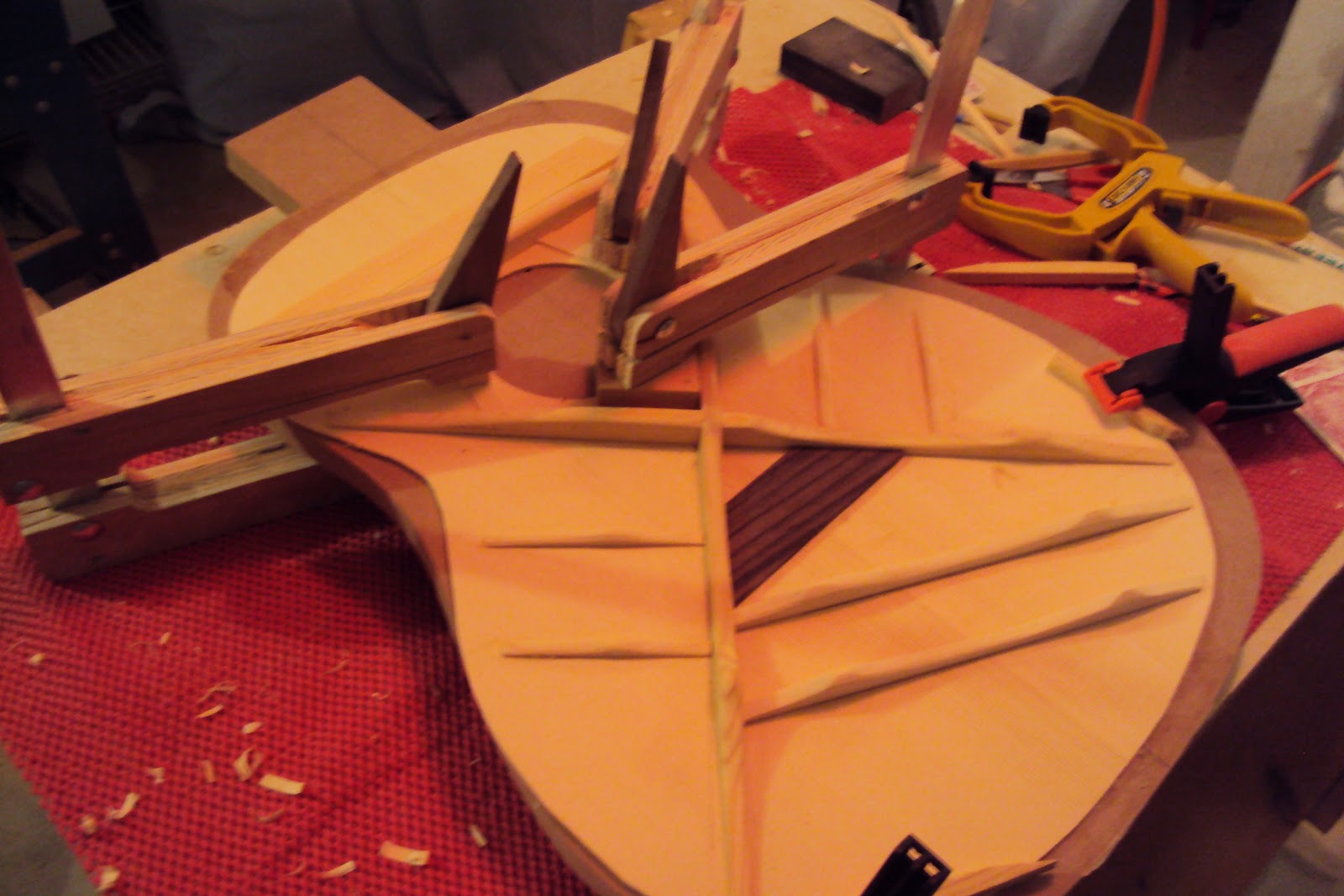
Sorry for all the bad photos. The final product. You can see a litle reveal betweed the work board and the back because the radius doesn't allow the back to sit flat.


Starting on the Back - the Back Reinforcement

After what seems like forever I am finally ready to work on the back. Like the front the back requires bracing and the bracing needs to be let into the sides. What should make this a little easier is all the bracings are perpendicular to the center line so I won't have to account for the same extreme angles the x braces created on the top.And I'm past the steepest part of the learing curve on constructing bracing (so he says...).

I did a layout line down the center of the back - now I know why white pencils are a good idea for rosewood. I'll have to get some. Then I drew a light line down the center of each of the three center strip pieces. I did a practice glue and clamp up...


... and then let it rip. As Ken suggested I taped the center strip sections down so they didn't slip while clamping and I found a piece of poplar the  exact length of the back to use as a caul.


After the standard amount of dry time I removed the clamps and tape. One of the things you need to do for the back to nest correctly to the rim is to trim away the area that will be covered by the neck and heel blocks. Its pretty quick work with a pull saw and chisel.


Next is to trim out sections of the center reinforcement to allow the bracing to pass through. A nice snug fit of the bracing to the reinforcement is a show of good craftmanship. Following Ken's directlion I made a little jig that stradles the center strip and allows for a perfect perpendicular.cut with the pull saw. A couple of minutes of cutting and chiseling the back was reinforced and I was ready for the braces.

Thursday, October 21, 2010

Gluing on the Top and Discovering an Oops

Pretty exciting day - I hope to complete attaching the top to the rims.

Before I get too far into this step, I don't know if you noticed or not but I changed workbenches. My standard workbench is my table saw with a sheet of 1/2" MDF laid across it. I found, however, as I put in some long sessions that working above the mold so to speak, had me working at a height that became very uncomfortable for my back. I'm guessing but the table saw is around 32" tall and I have it on rollers so I can move it out of the way. The rollers probably add 2". The the mold is sitting on top of that. When I make saw horses the legs are 30" but considering the leg angle they're actually about 28" tall. That 6" makes all the difference in the world. So now I have two saw horses with an old formica kitchen counter clamped across that is about, I don't know, maybe 24" x 30" and it is perfect. I did roll out a piece of that no skid matrix - I don't know the technical name for it - as the formica is a little hard and slippery. You can see the set up in the second picture below as well as the table saw in the background.

The mold is a key player in this step. Ken's direction is to hold the top in place with a couple of rubber bands. This will allow me to tip the mold on edge so I can see what is going on underneath without the top slipping around. Placing a couple of finish nails at the front edge of the top will help it orient length wise before you rubber band. I pre-drilled the top, dropped in the nails, laid the board on the rims and that was when I first noticed this hole in the front where the rims abut. What the heck? I pulled the rim out of the mold. There was nothing poking that would have done this, no sharp edges on the mold, no nails or screw protuberences. All I could think is that while I was shifting the rims up and down in the mold to work on the soudboard or kerfing I must have caught a little sliver in the wood that pulled out more around it as I stressed it. No worries, the neck will cover it but disappointing to have a flaw that I will always know is there.

Now the rubber bands. Nothing fancy. Just looped together two or three cheap bands that come with your mail.Oh, I did have to loctate some screws for the bands to strectch across. I suppose you can do as many as you like. I just did these three feeling two diagonals and one cross was adequate - plus I ran out of rubberbands!!!

Now that I can hold the top on securely I can easily get inside the body to mark where the bracing intersects the rim. The rim and kerf lining will be trimmed out to let the bracing "nest" in the trimmed out area and the sound board will seat flush to the rims.

Prior to trimming the rims I sanded down the bracing so that where ever it would contact the rim it was only one popsicle stick tall (about 1/8" I think). This is critical because the binding will have to cover the thickness of the sound board plus the depth of this notch when it is installed.

This began a series of back and forth mark the rim, trim some out, test fit the bacing in the slot, sand down the bracing, mark again, trim again, test fit again. I was going very slowy and cautiously, especially in light of my two latest mishaps. I finally ended up with a nice fit. I was actually pretty pleased with the craftmenship  on a couple and not so pleased on others - par for the course. One slot on the top edge is too long and too deep.I thought I would have to get creatiive but it looks like the binding will cover it well enough.

This one I like:                                                                   These two I don't like:

 Great, the soundboard fits the rims nice and snug. Its time to glue and clamp. Remember the dry fit and test clamp routine. Absolutely critical here. You are gluing the entire soundboard all at once. I don't know about anyone else but as a first time acoustic builder I was very intimidated by this step. There is no return from even the slightest mishap here.

The KMG kit provides a clamping caul for this operation. Its a piece of MDF cut oversize to the shape of the soundboard. You drill a series of holes (pre-marked) around the perimeter and this becomes the clamp as you drive a series of screws through the holes into the mold. As the screws tighten the caul presses the top and rim together. Go slowly  and tighten the screws evenly and you will get a great result. Since I've gotten into this I have read a lot about this step in the process and I am aware that there are several methods to clamp the soundboard to the rim. While this method is extremely simple, it is totally practical. This has a great appeal to me as a New Englander and my appreciation for Yankee thrift (and I'm not talking baseball).

I was so nervous about this step that I went through the dry run process a few times. Snugging the sound board went smoothly and so did attaching the caul but because I was hand tightening the screws I was concerned that it was taking me way too long to finish. I wanted to try to get even pressure more quickly. On the second trial I used a combination of clamps and the screws.


I felt like that worked a lot better for me. Here is the final glue up and clamping.


The glue set overnight and then I used a trim bit in my laminate trimmer to flush the top and rim. I did the recommended clockwise step cuts first but did not take a pic of that.


Still a lot more sanding and clean up to do but this is the interior with the soundboard attached:


I am now up to 35 hours and feeling like quite the slow poke.

Wednesday, October 20, 2010

More on the Top... Learning from My Mistake

With the cross brace installed it was time to shape and fit the two bass bars. The bars came on a single piece of wood with the scallop shape diagramed out. Sorry - I failed to take pictures of this... but this is what they look like when clamped in place. One thing that is hard to tell from the photos is that I saved the curved scallop cuts and was able to use them as cauls when clamping.

Bridge plate, check; cross bracing, check; bass bars, check,. Without going in to a great deal of description the side braces, shoulder brace, another brace I don't know the name of and the sound hole reinforcements are all installed in a similar fashion:


The last step in installing the bracing was to round over all the braces. I don't beleive there is any reason sound wise to do this (probably wrong on that) but it is definitely a craftmanship consideration.


and I'm in for about 30 hours at this point.

Tuesday, October 19, 2010

more on the Top... Preparing the Bracing and a Royal Screw Up

This summary is not available. Please click here to view the post.

Starting on the Top - Install the Rosette

One of the decorative elements to an acoustic guitar is the trim installed around the sound hole called the rosette. Rosettes can come in all sorts of materials, colors and patterns. Some incredibly intricate and some fairly basic. Some are three dimensional and need to be let into the wood and some are stickers that are just applied. I think professional luthiers take great pride in the rosette and really add their personal touch to this element. The KMG kit includes a pre-made rosette and the soundboard has already had the routing completed around the sound hole.

First things first. Make sure you have the right helper:


Just kidding, the cat really likes to sit in cardboard boxes and eat the build instructions. But its nice to have someone to listen when I'm muttering to myself about the work.

Once the rosette is glued to the sound board clamping can be somewhat ackward. Some recommend simply weighing it down - I saw a concrete block used in one example. Ken suggests and I agree that there is a more elegant solution for this.

Start with two pieces of MDF, three carriage bolts and three corresponding wing nuts. The idea is to sandwich the sound board / rosette between the MDF pieces, bolt the MDF together and tighten the bolts to compress the rosette to the wood. I have MDF laying all over the place but no carraige bolts and wing nuts. There was no way I was making a trip to Agent Orange just for this. But I do tend to save everything and this time it paid off. I snooped around my shop area and found some bolts, washers and nuts on an old ski rack I had made to fit in the back of my pick up (back in the day when I owned a truck and skiied, niether of which I do anymore) that would work perfectly. So I pre-drilled the MDF, countersunk one side for the screw heads so it would lie flat and was all set.

I gathered all the usual suspects:


Installing the rosette could not have been simpler. I was anticipating something much more complicated but I had to do very little sanding before I had a nice snug fit. I had a tube of Duco glue which is the preferred glue for wood rosettes - I believe because it holds well and dries clear. I squeezed a few drops, spread it out with a little popsicle stick, dropped in the rosette and clamped it up. I did put a layer of saran wrap between the rosette and the top layer of MDF to make sure any glue squeeze out would not stick to it.


and the finished product:. The gap is ok - it will be covered by the fret board when the neck is installed.